


Cindo Alves examines the importance of cabling in effective fibre-optic installations in the final part of the three-part series on the benefits of fibre-optics.
The purpose of the cable is to protect the optical fibres. Fibre-optic cable is available in different constructions that are determined by the number of fibres, size requirements and the environment it is to be installed in. Choosing the right fibre-optic cable is critical to the success of the design, as it will affect how easy it will be to install, terminate and splice.
This article concentrates on basic cabling plant design concepts to give you a clear idea of how fibre optic systems are built. In addition, we will be covering basic installation, testing and maintenance in order to insure the cabling plant has been installed as specified. These basic principles will help develop your ability to evaluate system designs and develop system concepts that work.
First, some definitions of words we will use:
* Cable – Designed to protect the optical fibres and is the heart of any cabling plant. Fibre-optic cables are available in various configurations for indoor and outdoor uses.
* Connectors – Connectors are used for connecting fibre-optic cable to the transmission equipment and patch panels. Connectors are available in a variety styles and termination methods.
* Splices – Used to repair an optical fibre and/or connect two fibres together with minimal loss. Splices can be fusion or mechanical type.
* Patch Panels – Allows system flexibility and is used for making moves, adds and changes in the cabling plant.
Choosing the right cable
As a design professional, you have the job of selecting the right cable construction type for the environment the cable will be installed.
There are two primary types of fibre-optic cable; tight buffer cables that are used for indoor environments, and loose-tube cables which are used in outdoor plant environments.
All cables share some common characteristics. Optical fibres used in cable designed for indoor applications have tight buffer coatings to provide increased tensile strength, provide protection and allow for ease in termination. Outdoor cables are designed with fibres in a loose tube construction filled with moisture blocking gel to prevent water ingress. In addition, fibre-optic cables typically have some type of strength member; for instance, an Aramid yarn such as Kevlar fibre to add additional strength during cable pulling. As a cable increases in size, more substantial strength members such as fibreglass or steel rods are added for even greater strength.
Indoor cables
Cables installed inside buildings do not need to be constructed in a manner to protect the optical fibres from harsh climates because they are typically installed in a controlled environment. However, the cable construction does have to meet established fire codes such as those listed in the National Electrical Code (NEC) or local municipality’s codebook.
The following three cable constructions are most commonly used for indoor applications:
* Simplex/Duplex.
* Breakout.
* Distribution.
Simplex/duplex cable
A simplex cable is constructed with one optical fibre that has a PVC buffer that is tightly extruded around the fibre. The cable also utilises a Kevlar fabric strength member and has a PVC jacket. These cables are typically 3 mm in diameter.
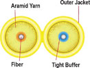
Breakout cable
A breakout cable is basically multiple simplex cables bundled together under one jacket. This type of construction allows the cable to be ‘broken out’ into multiple fibres with each one having its own sub-unit jacket. This construction provides extra protection for each fibre and allows for easy termination.
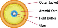
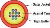
Distribution cable
A distribution cable contains individual buffered fibres with no sub-unit jackets. This allows for a smaller cable size and each optical fibre can be directly terminated. This is the most popular cable construction used for indoor cabling plants.
Outdoor cable
Cables installed outside, otherwise known as outside plant cabling, may be installed in harsh, unprotected environments such as directly buried below grade, placed in conduit, or strung aerially from building to building.
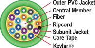
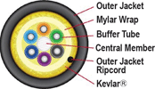
Loose tube cable
This type of cable construction is designed with one or several fibres together inside small plastic tubing. This type of cable is typical for outside plant environments as it can be pulled long distances as there is usually a steel or glass epoxy central strength member and sometimes the addition of an Aramid strength member for added strength.
The fibres are placed loosely in small tubes and each tube is filled with a water blocking gel. This allows for a high fibre count, while keeping the overall diameter of the cable small.
Cable plant design
There are several considerations that the design professional must keep in mind while laying out a cabling plant for the design. Here are some items you may want to consider placing in your design specification.
Cable length
When designing a system, always expect the unexpected. Cables will get damaged or cut and your customer may want to make moves, adds, and changes to the system. Adding extra cable in the run will protect you when these unexpected issues crop up.
Rule of Thumb: Allow for at least 10 to 20 metres extra of cable slack in order to handle cable repair and enable equipment relocation with a minimal amount of splicing.
Fibre count
Since the design will require a certain amount of fibres, it is always a good engineering practice to plan ahead for future expansion and transmission capacity. Guidelines vary; however as a rule of thumb the designer should specify 50% more fibre than what is needed in the design. To provide extra insurance you may want to specify as much as 100% more fibre than needed.
Rule of Thumb: Identify how many fibres are needed for the current design. Identify with the customer their plans for future changes or expansion to the system. Add the current fibre requirements and the future requirements together. Then take this number and add 50% as a buffer.
Splicing
Splicing is a method of joining two fibres together. Splicing may need to be completed when splicing for long cable runs. Splicing also becomes very important for system restoration in repairing a problem and getting a system ‘up and running’ as quickly as possible.
Test equipment
There is a variety of test equipment that is available for testing a fibre-optic system. The power meter and the OTDR are the two workhorses when it comes to fibre-optic testing. It should be a requirement in the design that the installer provides test results on all optical fibre used in the system, no matter whether it is new or existing fibre. The power meter will provide an overall end-to-end optical path loss reading of the optical fibre under test and can be compared to the optical path loss calculation performed earlier in the design stage.
OTDR
OTDR stands for optical time domain reflectometer. This unit provides a graphical representation of the fibre’s performance. This test equipment is great for confirming cable lengths and also to determine the location of fibre breakage when there is no physical indication of a break along the cable jacket. Either piece of test equipment will work to provide basic fibre optic acceptance testing; however, on higher end systems it may be desired to have the system fully tested with an OTDR with full documentation.
System testing
There are three basic tests that should be performed with every fibre-optic system to ensure the trouble-free installation and long-term reliability and performance of any given system.
Cable acceptance testing – Before installation of the cable, it is suggested that the installer test the fibre-optic cable with an OTDR while it is still on the original spool used for shipping. This will allow the installer to confirm the length of the fibre and also its performance characteristics. In addition, any damage internal to the fibre would be discovered before the cable is installed. All test result findings should be documented for reference.
End-to-end loss testing – After installation of the cable, the installer should use a power meter or OTDR to perform an overall end-to-end loss test of the optical fibre. This test should be performed at both optical wavelengths for the given fibre under test to ensure optimum performance of systems using more than one wavelength such as WDM equipment.
System performance testing – After connection of the fibre-optic transmission equipment, the fibre-optic transmitter output power and receiver input power should be tested with a power meter to ensure compliance to the design specification. All test results should be documented.
Important note: NEVER look into the end of an optical fibre when using a laser light output. Permanent eye damage can occur.
For more information contact Cindo Alves, Alves Audio Visual Services, +27 (0)82 414 2146, [email protected]


© Technews Publishing (Pty) Ltd. | All Rights Reserved.
 printer friendly version