


Cindo Alves unravels the mystery and benefits of fibre optic cabling in this the first of a three-part series.
Over 20 years ago, when International Fibre Systems started manufacturing and marketing fibre-optic equipment to the security market, most design professionals were designing their systems with copper cabling.
Fibre-optic transmission was still a mystery to many and misconceptions regarding the technology were plentiful. Some design professionals thought that optical fibre was only needed for long distance, others thought the technology was too expensive or there was concern about fibre being fragile and difficult to terminate or that you had to have a Ph.D in fibre-optic technology to be proficient in system design.
Today, those misconceptions are being dispelled as consultants, integrators and end users alike are discovering the many advantages of deploying fibre-optic technology into their systems.
Companies are seeking out design professionals who are well versed in the latest fibre-optic transmission techniques. In today's competitive environment, it is necessary to become recognised as an experienced designer of fibre-optic transmission systems. As a design professional, it is their responsibility to design an efficient, cost-effective system for the client. It is important for the designer to fully understand the limitations of and the tradeoffs between various elements of the system.

Understanding the basics
Fibre-optics is a technology whereby an electronic signal is modulated on a beam of light and transmitted down a small glass fibre strand with minimal signal loss. Fibre-optic transmission is one of the best transmission methods available, but to some design professionals it still remains a big mystery. Hopefully this article will help demystify some of these misconceptions and provide an overview and sound foundation on which to build the reader's knowledge of fibre optic technology.
Engineers in a multitude of different industries today are utilising fibre-optic technology in varying applications due to the many advantages available with this exciting technology. Here are some of the common advantages that are realised when implementing fibre-optics as the transmission medium in the design of any communication system.
EMI/RFI immunity: Because the signal is being transmitted with light, fibre-optic transmission is immune to electromagnetic (EMI) and radio frequency interference (RFI) which is a common problem with copper-based transmission systems.
Low attenuation: Optical fibre can provide longer distances vs. conventional copper cabling without costly repeaters. Current multimode fibre losses are as low as 1 dB/km and single-mode fibre losses can be as low as 0,2 dB/km.
High bandwidth: Fibre-optics has been bandwidth tested at over 350 billion bits per second over a 100 km distance. Theoretical rates of 200-500 Trillion bits per second are obtainable.
Light weight and small size: A 12-strand fibre-optic cable operating at 140 Mb/ second and weighing 65 kg per km can handle as many voice channels as a 900 twisted-pair copper cable that weighs 8 tones per km. Smaller size provides better conduit utilisation through the use of inner ducts with less physical effort.
Secure transmission: Because fibre is a dielectric, the fibre does not radiate electromagnetic pulses, radiation, or other energy that can be detected. This makes the fibre cable difficult to find and methods to tap into the fibre create a substantial system signal loss thus providing easy detection.
Lightning and ground loop protection: Optical fibre is totally immune to virtually all kinds of interference, including lightning, and will not conduct electricity. Therefore, it can come directly into a building along with high-voltage electrical equipment and power lines. You can also think of fibre-optics as a big opto-isolator between buildings as it also will not create ground loops of any kind.
No cross-talk or shorts: Since the fibre is glass and does not carry any electrical current, radiate energy, or produce heat or sparks, the signal is kept within the fibre medium therefore eliminating cross-talk problems or shorts. It is also ideal in environments susceptible to explosion risk due to any electrical failures.
NEC installation flexibility: Under NEC code 770-52 Installation of Optical Fibre and Electrical Conductors, with Conductors for Electric Light, Power, or Class Circuits, non-conductive optical fibre cable shall be permitted within the same cable pathway used for electric light, power, or class one circuits operating at 600 Volts or less, therefore allowing the use of existing cable trays and eliminating the need for additional low-voltage conduit and trays.
Some fibre-optic units of measurement
dB - Decibel, a logarithmic ratio measurement distinguishing the percentage of signal attenuation between the input power and output power. Attenuation (loss) is expressed as dB.
dBm - Decibels relative to one milliwatt of power. Numbers below one milliwatt are expressed in -dBm and numbers greater than one milliwatt as +dBm.
Micron - One millionth of a metre. There are 25 microns to one thousandth of an inch (,001). Microns are used in the measurement of a fibre size.
Nanometer - One billionth of a metre, the term nanometer is used to express the wavelength or frequency of the transmitted light.
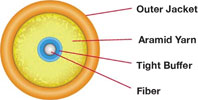
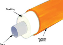
The optical fibre
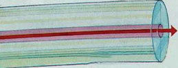
The two key elements of an optical fibre are the core and cladding. The core of an optical fibre, which is made of glass, has a higher index of refraction than the surrounding cladding which has a lower refractive index. Therefore, when light is injected into the glass core at the correct angle, it will reflect off the cladding back into the core and will continue doing so as it travels forward in the fibre. In other words, the light cannot escape from the core area and the optical fibre acts as a light pipe or an optical waveguide.
There are two common types of optical fibre in use for today's communication systems; single-mode fibre and multimode fibre.
Single-mode fibre
The term single-mode is derived from the fact that the core is so small (only about 9 microns - a micron is one one-millionth of a metre) that only a single mode or path of light travels through the core of the fibre.
Single-mode fibre characteristics are low attenuation and high bandwidth; this makes single-mode fibre an ideal choice for long distance transmission or applications where a high volume of information is being transmitted.
Examples of applications that may use single-mode fibre are as follows:
* Long distance CCTV.
* Telecommunications.
* CATV systems.
* Intelligent transportation systems.
* Railways.
* Large airports.
* Large mining environments.
Multimode fibre
The term multimode is derived from the fact that a larger core, usually 50 or 62,5 microns, has multiple modes or paths of light travelling through the core of the fibre.

Multimode fibre does have inherent characteristics, such as higher attenuation and limited bandwidth performance as compared to single-mode fibre. However, if the systems requirements are within the limitations of multimode fibre, this will often be a better choice for the design professional to use, as multimode fibre optic equipment is more cost-effective than single-mode equipment due to the lower cost in using LEDs vs. laser diodes to generate the light energy, thus reducing the overall system installation cost.
Examples of applications that may use multimode fibre are as follows:
* CCTV.
* Access control.
* General security/fire alarm.
* Building automation.
* Data networking.
* Audio transmission.
Optical wavelengths
Optical fibre operates at different optical wavelengths. Wavelength is simply an optical term for the colour or frequency of light being transmitted in the fibre. Fibre-optic equipment, for use in communication systems utilises light in the infrared region that is invisible to the human eye. Optical wavelength is measured in nanometers (nm) meaning one-billionth of a metre.
Multimode fibre generally operates at two primary wavelengths in the light spectrum, 850 nm and 1300 nm, for optimum transmission. Since the actual frequency may vary slightly. Optical designers sometime use the term windows (ie, the transmitter is utilising the 1300 nm metre window). Single-mode fibre generally operates at 1310 nm and 1550 nm wavelengths for optimum transmission. Optics operating at 850 nm are typically not used for transmission on single-mode fibre.
Attenuation
Attenuation represents the loss of light or power in an optical fibre. When using an optical fibre, attenuation is dependent upon the operating wavelength; therefore wavelength and attenuation are directly related to each other as the longer the wavelength the lower the attenuation. In addition, the size of the optical fibre's core also affects the attenuation of light or power in an optical fibre. Attenuation is measured in decibels (dB) and the loss in an optical fibre is expressed in dB per km. There are two different types of losses that can be categorised in regards to attenuation.
Intrinsic loss - are losses that are internal to the fibre. Factors such as absorption, scattering, fibre core variations, and micro bending create such losses. Since these types of losses are internal to the fibre, the designer or installer has little control over this type of loss.
Extrinsic loss - are losses that are external to the fibre. Factors such as connector and splice losses, external attenuators, optical couplers, macro and micro bending create such losses. The designer and installer have much more control over these losses and should be taken into account when designing a fibre-optic system.

Bandwidth
Bandwidth is the amount of information that can be transmitted on an optical fibre. Typical bandwidths for common fibres range from a few MHz/km for very large optical cores, to hundreds of MHz/km for standard multimode fibre and thousands of MHz/km for single-mode fibre. An important concept to be aware of is that as the length of the fibre increases, its bandwidth will decrease proportionally. For example, an optical fibre that can support 500 MHz bandwidth at a distance of 1 km will have only a 250 MHz bandwidth at 2 km and 100 MHz bandwidth at 5 km. Likewise, if the length of the fibre decreases, its bandwidth will increase proportionally.
This concept is critical when designing a fibre-optic system as increased cabling distance can affect overall bandwidth capability and bandwidth can then become the limiting factor in the design vs. attenuation.
In the next issue we will continue our examination of fibre-optics and delve further into fibre systems and components.
For more information contact Cindo Alves, Alves Audio Visual Services, +27 (0)82 414 2146, [email protected]


© Technews Publishing (Pty) Ltd. | All Rights Reserved.
 printer friendly version